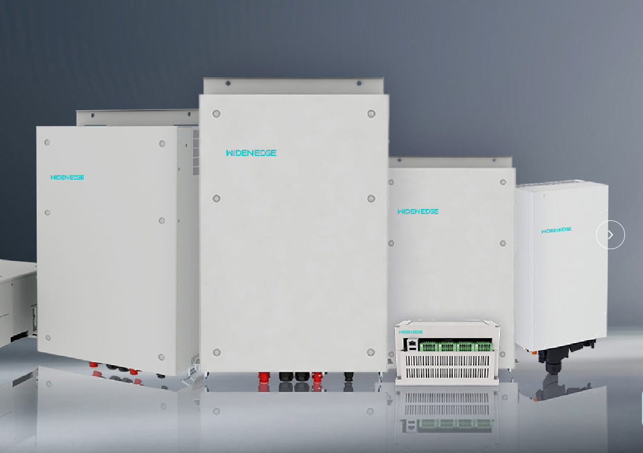
Comparative overview and deployment risk
Choosing protection features isn’t about collecting checkboxes; it’s about matching failure modes to site risk and operational goals. For a 150kW battery inverter, some protections are non-negotiable, others trade cost for resilience. I’ve seen systems fail not from exotic faults but from ignored configuration errors during commissioning on remote microgrids in the Philippines — that context shapes which protections you prioritize.
Must-have protections (safety and survivability)
- Overcurrent/short-circuit interruption: device must list a clear interrupt rating and trip curve. Confirm I²t handling for expected fault currents; vendor test certificates are decisive.
- DC isolation and arc-fault detection: fast detection of DC arcing and automatic isolation to prevent thermal propagation inside battery rooms.
- Ground-fault and residual-current monitoring: continuous detection on DC and AC sides, with selectable trip thresholds and automatic logging of fault location or channel.
- Temperature derating and thermal protection: explicit derating curves by ambient; verify operation at peak site temperatures and the presence of thermal cutouts to avoid thermal runaway.
- BMS interface and charge/discharge limits: secure CAN/RS485 or Modbus links to the battery management system enforcing SOC, charge rates and cell-level alarms.
These features prevent catastrophic outcomes and are non-negotiable for safe 150kW deployments.
Strongly recommended protections (operational continuity)
- Anti-islanding and reconnection logic: certified behavior against unintended grid disconnects; look for standards compliance such as UL 1741 SA or equivalent functional descriptions.
- Surge protection (SPDs) on AC and DC rails: coordinated protection levels and replaceable modules. Coastal, industrial, or frequently storm-affected sites need higher nominal protection.
- Soft-start, sequencing and controlled ramp: avoids inrush stress that can trip upstream protections and reduces mechanical stress on contactors.
- Redundancy and parallel-operation safeguards: active balancing of load sharing, automatic isolation of a failed unit and clear arbitration rules for bus reconnection.
- Firmware management and secure update paths: integrity checks, rollback capability and cryptographic signing prevent accidental or malicious destabilization.
These reduce downtime and require clear vendor documentation to validate real behavior under fault conditions.
Optional but useful protections (site-specific value)
- Harmonic mitigation and low THD mode: valuable for sensitive loads or when generators run in parallel with the inverter.
- Transformer-based galvanic isolation: improves surge and ground-fault behavior but adds weight and cost; choose if site grounding is uncertain.
- Advanced event analytics and edge logging: improves root-cause diagnostics when combined with time-synchronized power and temperature logs.
- Climate-protection options: extended IP rating, heaters for cold climates and corrosion-resistant coatings for salty air.
Consider these when the site has specific environmental or load requirements; they’re not automatic must-haves.
Comparative checks and acceptance criteria
- Specification transparency: supplier must publish trip thresholds, time-to-trip, test reports and the worst-case fault energy. Prefer explicit numbers over vague phrases.
- Standards and certification: verify references to IEC/EN safety standards and evidence of laboratory testing; field test reports are a plus.
- Failure mode behavior: the device should define safe failure states (open-circuit, controlled shutdown) and the effect on battery state and loads.
- Response timing: for arcs and ground faults, response in the millisecond-to-second range matters; compare measured response times, not just advertised protection types.
- Maintainability: replaceable SPDs and contactors, local diagnostic LEDs and clear fault codes speed restoration.
Rank vendors by how many of these acceptance criteria they meet and by the clarity of their test evidence.
Testing and common commissioning mistakes
- Commissioning tests to mandate: simulated short-circuit tests, anti-islanding verification, SOC boundary enforcement, thermal cycling and BMS communication loss scenarios. Record timestamps and fault traces.
- Common mistakes: leaving default trip thresholds, skipping thermal derating validation, failing to simulate BMS comms loss, not verifying SPD coordination, and assuming factory firmware settings match site needs.
- Practical checklist item: force a controlled fault and verify how the inverter isolates, logs the event and reports to the supervisory system.
Run tests at representative ambient conditions, and never accept “works in the lab” as sufficient evidence for field use.
Alternatives and selection trade-offs
Compare topology and integration choices against project goals:
- Transformerless vs transformer-based: transformerless units are lighter and more efficient; transformer-based units add isolation and robustness in dirty or high-surges sites.
- Integrated BMS vs external BMS: integrated BMS simplifies commissioning but can lock you to vendor cell strategies; external BMS gives flexibility but demands stable communication and clear APIs.
- Centralized 150kW unit vs modular string approach: a single 150kW inverter reduces footprint but concentrates single-point risk. Modular inverters distribute failure risk and simplify hot-swap repairs.
For off-grid or islanded systems reference, check models used across common deployments of off grid solar inverters to see which topologies proved resilient under limited maintenance regimes.
Final synthesis
Decide on protections by mapping likely fault scenarios to measurable device capabilities: define trip thresholds, insist on documented tests, and require clear failure modes. Choose features that reduce repair time and prevent escalation of a single fault into a safety incident. That pragmatic mapping — not marketing claims — is what separates robust field systems from intermittent performance; vendors who supply test evidence and practical configuration guidance make system survival predictable, as demonstrated repeatedly by teams working with WidenEdge.